Logic Gates
 Ultimately
to build functional computing machines or Intenet routers, we need to be able
to turn electron flow into logic and logical decision making.
This requires the integration of various logic gates within a transistor array.
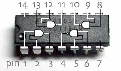
A typical 14 pin array is shown to the right. Ultimately
to build functional computing machines or Intenet routers, we need to be able
to turn electron flow into logic and logical decision making.
This requires the integration of various logic gates within a transistor array.
A typical 14 pin array is shown to the right.
EACH integrated circuit (IC) has a specialized function.
The 4011BCN shown above is known as a Quad 2-Input NAND Gate IC.
It incorporates NPN and PNP transistors and diodes in order to perform logical calculations
ELECTRICAL current passes through each pin on the chip and performs functions along the way.
For example, Pin #14 connects positive electrical voltage to the IC,
and Pin #7 connects negative electrical voltage.
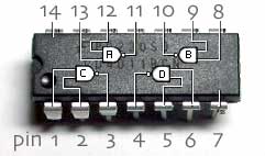
We use symbols (A, B, C, D) to represent various electronic channels
through the IC. Each of these different symbols represents a logic
gate as shown below.

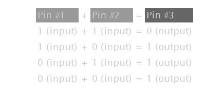
For example, suppose pin #1 and pin #2 were each sending input signals
(e.g. electricity) into gate C, which would then be output at Pin #3 as
either a zero or a one.
The 4 possible combinations for Pin 3 output would then be:

Hence this gate, can only output a level of zero under one specific
input condition. The other logic gates work under similar principles and
therefore can be programmed to make decisions. The more gates that
are present in the circuit, the more complicated the decision making
can become.
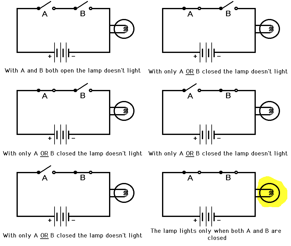
The following animation represents the logical functionality of an AND gate
where
- Switch A corresponds to AND gate input A
- Switch B corresponds to AND gate input B
- An open switch corresponds to 0 on the input line
- A closed switch corresponds to 1 on the input line
- The lamp corresponds to the AND gate output, unlit being binary state
0 and lit being binary state 1

An OR gate would work like this:

Study these resources:
A simple decision making circuit
and
This logic gate primer
and
These animated gates
These concepts are not difficult. They are all based on a set of truth tables in which a bit of 1 represents true and a bit of 0 represents false. Combinations of 1's and 0's then turn into logical decisions involving AND OR NOT XOR (which stands for exclusive) kinds of gates.
|