While there are literally hundreds of wave energy devices that have been conceived, most of them are small variations on basic engineering and/or physical designs. Since the Power Bouy was discussed in the previous material, we will leave that device out of the present discussion.
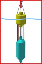 However, we do note that Power Buoys don't necessarily need to be "anchored" near the shoreline. The "Bob", originally created in Ireland is the case of a free floating Buoys held in place by a large ballast. Still, however, one needs to get an
electrical cable to Bob. Bob has now evolved to be WaveBob - go there and watch their marketing video. While this appears to be somewhat viable (other than the material costs) the robustness of this network of bobbing Bobs in high seas remains a concern. However, we do note that Power Buoys don't necessarily need to be "anchored" near the shoreline. The "Bob", originally created in Ireland is the case of a free floating Buoys held in place by a large ballast. Still, however, one needs to get an
electrical cable to Bob. Bob has now evolved to be WaveBob - go there and watch their marketing video. While this appears to be somewhat viable (other than the material costs) the robustness of this network of bobbing Bobs in high seas remains a concern.
The Oscillating Water Column (OWC)
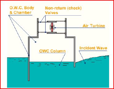
This is a relatively simple concept and is also called an "Air Piston". The basic idea is that the incoming water wave pushes a column of air in front of it which in turn spins a turbine. The overall throughput of an OWC depends on a) the frequency of incoming waves and b) the size of the chamber. In general, these devices are very hard to scale up in size and can be destroyed by strong storms (see below) | |
The incoming wave basically pushes the water level up and displacing, and to some extent, compressing air, in a chamber that contains a piston which is used to the turn the crank on a generator.
When the water recedes, air rushes back into the chamber and the cycle starts again.
In principle these devices could be embedded in coastal headland topography. Tidal variations also figure prominently into the design since the lower part of the chamber should always have water in it. | 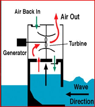 |
Some difficulties associated with OWC:
- The initial cost of the barrier wall/chamber construction is high due to the lack of access to coastal headlands/cliffs
- Zoning regulations protect this environment as rich marine life is often found there
- The device must withstand big storms
|  |
 This OWC device in Norway had a lifetime of 4 years before being destroyed by a big storm. In general, it would seem inevitable that these embedded objects would
be destroyed by strong (usually winter) storms that generate excessive
wave heights. The nominal power output of this "can" was 500 KW and the bottom 3.5 meters of the chamber (above sea level) was made of 30,000 tons of concrete and the top17.5 meters was made of steel. So this is a very material intensive device that still was destroyed.
Indeed this issue of scale is important for the OWC. At 500 KW per installation you would need two per generated MW. So assume you constructed 200 of these along the Oregon coast (or roughly 1 per every 2.5 miles of coastline). This would still produce only 100 MW of power which is 1/4 of what Eugene needs. OWC's are not scalable at all.
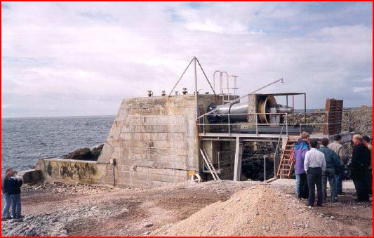
Installation of the Coast of Ishlay (UK)
 |  |
The tapered channel (TAPCHAN) is another proposed device. In this case a "funnel" directs the incoming wave into a temporary reservoir and the water drains out through a turbine house.
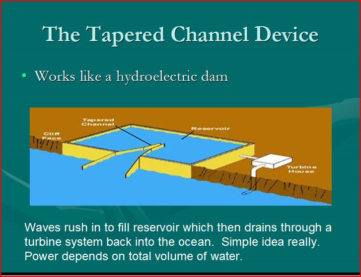
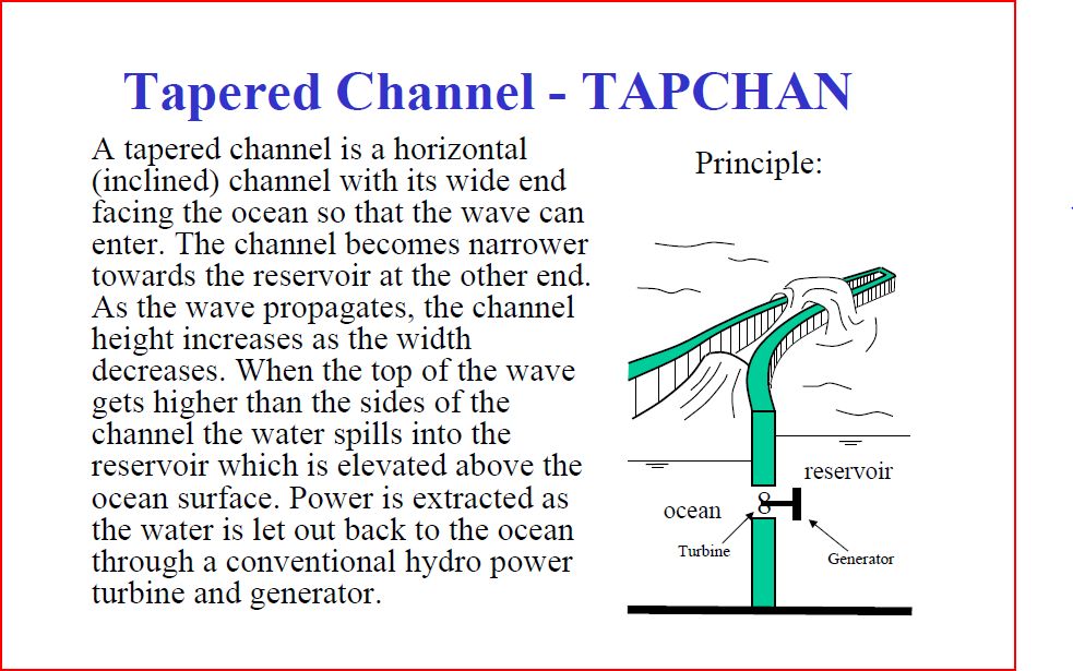
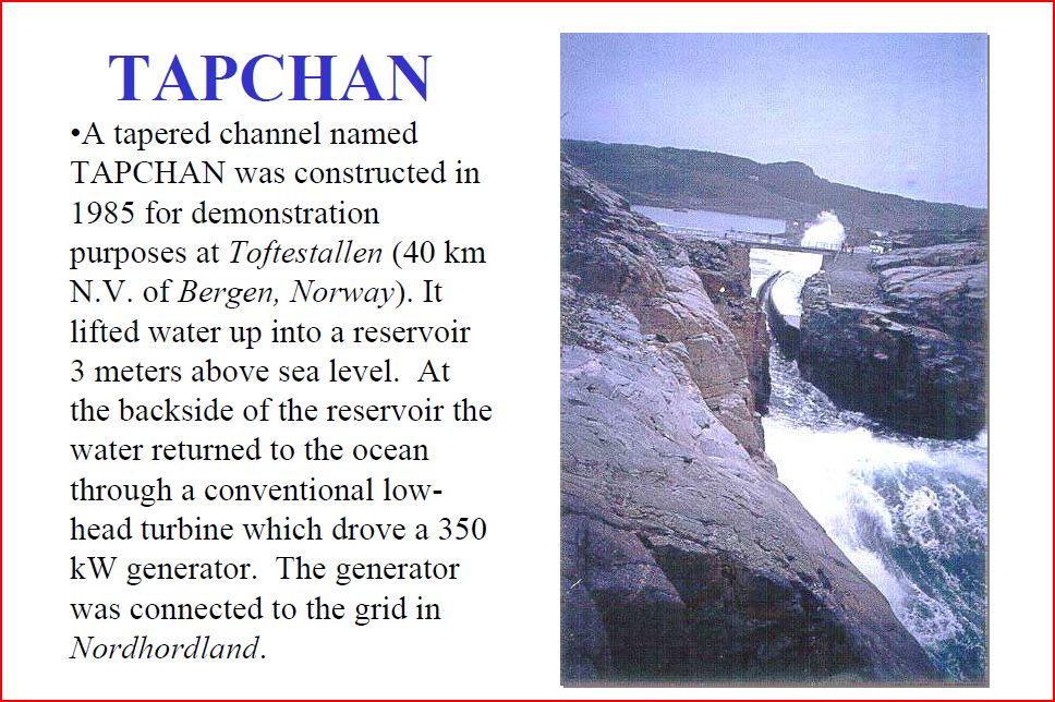
The Pros and Cons of the TAPCHAN Device include the following:
- This kind of project could be incorporated into new kinds of seawall or jetty or harbor protection projects. The TAPCHAN itself
could just be integrated into the structure.
- The average wave energy must be high in order to push all of the water into the reservoir or drainage channels.
- The reservoir needs to stay full and can't drain at low tides. This means at high tides a lot of the water pushed in will simple
spill over the top of the structure
- Projects like these have significant capital coast and if located directly on the short have a large footprint per MW generated since the depth of the reservoir will necessarily be shallow.
- These devices are likely not practical in most shoreline locations.
Overtopping Systems
This device is meant to operate with wave swells. The device is over-topped by an incoming swell and that swell drains our through a turbine outlet. In areas of high swell (the North Sea) a network of these devices could, in principle, generate GW's of electrical power. | 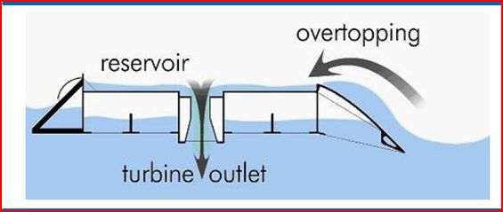 |
This device, known as the Wave Dragon, has two extended
arms that help guide the swell onto the platform into which there are 16 drainage ports that are each attached to a turbine.
Currently there are operating prototypes in the North Sea and off the coast of Portugal. | 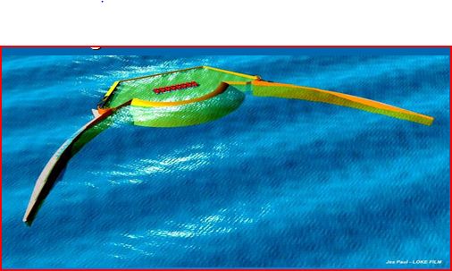 |
This is an actual working wave dragon. Each turbine is a single 4 MW generator and there are 16 per platform for a total platform throughput of 64 MW. (note that 64MW is the entire capacity of Nevada Solar One which requires 400 acres instead of less than 1 acre for
the Wave Dragon). 25,000 individual wave dragons then would produce 10 GW of electrical power. The principle challenge is then in the form of grid connections. Overall, however, wave dragons look like scalable technology that one day may become common. | 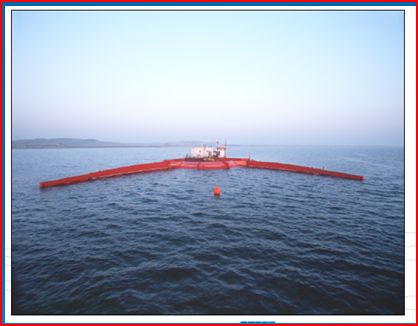 |
Hinged devices, also known as Sea Snakes, and technically known as Pelamis devices have a large potential. A
Pelamis Array has been operating off the coast of Portugal since late 2008. The specifics about each device:
- unit capacity is 750 KW (device weighs also 750 tons)
- Each is 150 meters long and 3.5 meters wide
- Portugese project uses 7 tubes to generate 5.25 MW.
| |
In principle, these floating arrays of Pelamis tubes are quite a scalable approach. Since the waves/swells are continuous, the surface footprint efficiency could be quite high. One square km could contain 500 of these devices (in an array of 5x100) which would represent 375 MW of continuous electrical power. Again, grid connections become the limiting factor. | 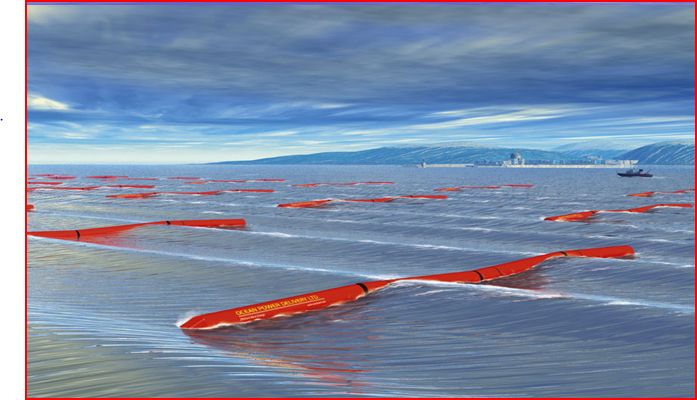 |
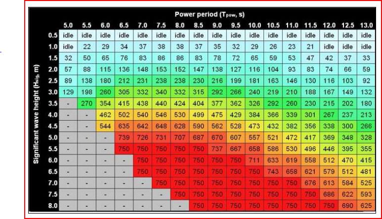
In addition, the Pelamis device can yield its 750 KW of continuous power under a fairly large range of wave conditions. If place at a site whose average conditions are favorable, the Pelamis device would operate in a very reliable manner.
Wave Rollers
The last device we will discuss are known as Wave Rollers and these can be place on the bottom of the ocean near shore. This has two principle advantages: a) they are out of site and do not influence surface ocean activity and b) grid connections are much easier to make. However, the bottom part of an incoming wave has considerable less energy than the surface portion of that wave.
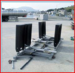
A wave roller is essentially a hinged device that is displaced back and forth as the bottom of the wave comes in and goes out. This device does have the advantage that's its dual cycle as its power by both the incoming wave and the outgoing draw. Three 100KW units of the design shown to the right were deployed near shore at Peniche Portugal in 2012 and plans are to enlarge that array to 1 MW with a grid connection to the national electricity grid of Portugal. | 
 |
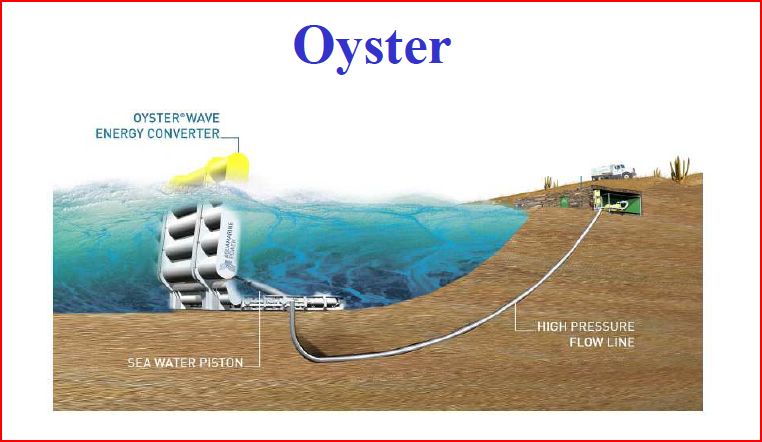 In 2009, off the coast of Orkney, the Oyster1 315KW prototype successfully operated for 6000 hours before the project ended. This technology has a lightly more favorable material intensity ratio as the 315KW unit weighs in at 200 tons or .7 tons per KW generated. That trial allowed Aquamarine Power to
develop the Power Oyster 800 . The 800 generates 800 KW of power through a flap 26 meters in length (50% larger than the original Oyster. These flaps can be made into an array. Current plans are to
array 3 of them to power a 2.4MW on shore generator. In 2009, off the coast of Orkney, the Oyster1 315KW prototype successfully operated for 6000 hours before the project ended. This technology has a lightly more favorable material intensity ratio as the 315KW unit weighs in at 200 tons or .7 tons per KW generated. That trial allowed Aquamarine Power to
develop the Power Oyster 800 . The 800 generates 800 KW of power through a flap 26 meters in length (50% larger than the original Oyster. These flaps can be made into an array. Current plans are to
array 3 of them to power a 2.4MW on shore generator.
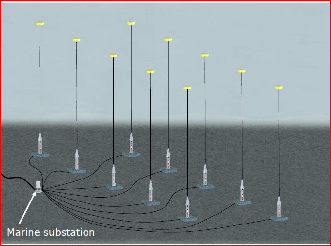 Finally one can imagine an array of "Point Absorbers" (these are similar to power buoys) anchored to the local sea floor which has an incoming grid connection.
The electricity is generate in the bottom portion of each column as the top "float" (the yellow thing) Bobs up and down. The advantage of this concept is that the electricity is generated at the bottom near where the grid connection is, instead at the top (like in the case of the traditional Power Buoy). Unit capacity basically depends on the diameter of the float, but there are structural limitations on the size of the floats so each unit will likely only produce on the order of 10s of KWs of power. Finally one can imagine an array of "Point Absorbers" (these are similar to power buoys) anchored to the local sea floor which has an incoming grid connection.
The electricity is generate in the bottom portion of each column as the top "float" (the yellow thing) Bobs up and down. The advantage of this concept is that the electricity is generated at the bottom near where the grid connection is, instead at the top (like in the case of the traditional Power Buoy). Unit capacity basically depends on the diameter of the float, but there are structural limitations on the size of the floats so each unit will likely only produce on the order of 10s of KWs of power.
In sum, there are many different designs to intercept wave or swell ocean power. Each design has its own limitations and its own ability to scale. On the surface, wave rollers seem the most practical but are the least efficient. The Sea Snake farm is likely the better solution however, that technology has the high material intensity of 1 ton per KW generated. Given all of these difficulties, wave energy is likely to remain a small contribution to the overall use of renewable energy technologies.
|