Solar Concentrator PV Systems
Basically use some optical system to focus Sunlight onto a PV Array


Basically use some optical system to focus Sunlight onto a PV Array
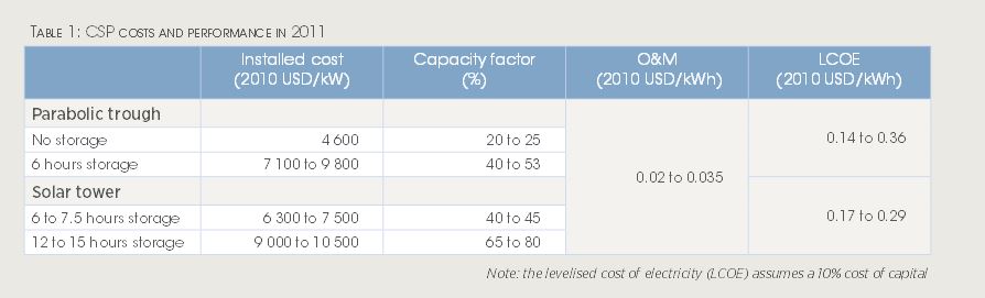
However, current projects are not proving to be cost effective:
As of end of 2011 in the US there was only 1.9GW of installed CSP (compared to 40 GW of wind).
There are other CSP projects in the world but they too are not yet cost effective.

The issue then becomes the reliability of the CPV components over time. Also CPV systems function best under clear sky, direct-sun conditions. Early installations were made in Saudi Arabia, Arizona and at Alice Springs, Australia.
Costs are a strong function of DNI (Direct Normal Irradiance):


The primary potential problem here is heat load and subsquent failure of the PV material.
Within CPV systems, the concentration rato can have high variance.
If light that falls on 100 sq. cm of reflector surface is focussed onto a 1 sq. cm surface of PV material, then the concentration ratio is 100. Current commercial design concentration ratios are in the range 200-300 suns.
Various Designs:
Fresnel Lens:


Advantage = simplest system and light weight. Focus is
"horizontal" and not parabolic.
Can be made Large or small
Linear Array for Power Tower


Point Focus Array:


Most
Expensive but can track the sun.
Solar concentrator technologies potential offers significantly higher gains at the likely expense of heat load failure.

Look, its a Jungle Gym ...

The Urban Brownfield Array (chicago)

Before the installation

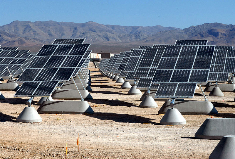
Current US largest installation (15 MW = UO campus load)
Installations in Eugene


Building Integrated (BIPV)


Many commercial systems now use something called a parabolic trough:  , Here the focus point of the parabolic trough is a receiver pipe. The pipe is filled
with oil (not crude oil) and is heated to about 400 C. This heat energy is then used to
generate electricity in a conventional steam generator.
, Here the focus point of the parabolic trough is a receiver pipe. The pipe is filled
with oil (not crude oil) and is heated to about 400 C. This heat energy is then used to
generate electricity in a conventional steam generator.

All renewable energy projects need to be evaluate in the units just presented!
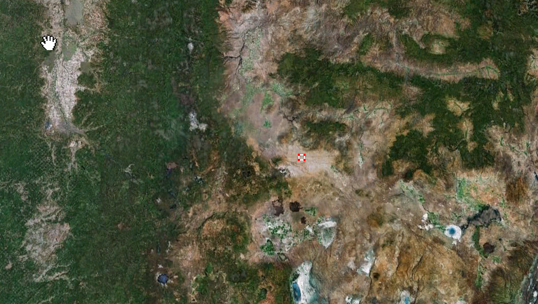
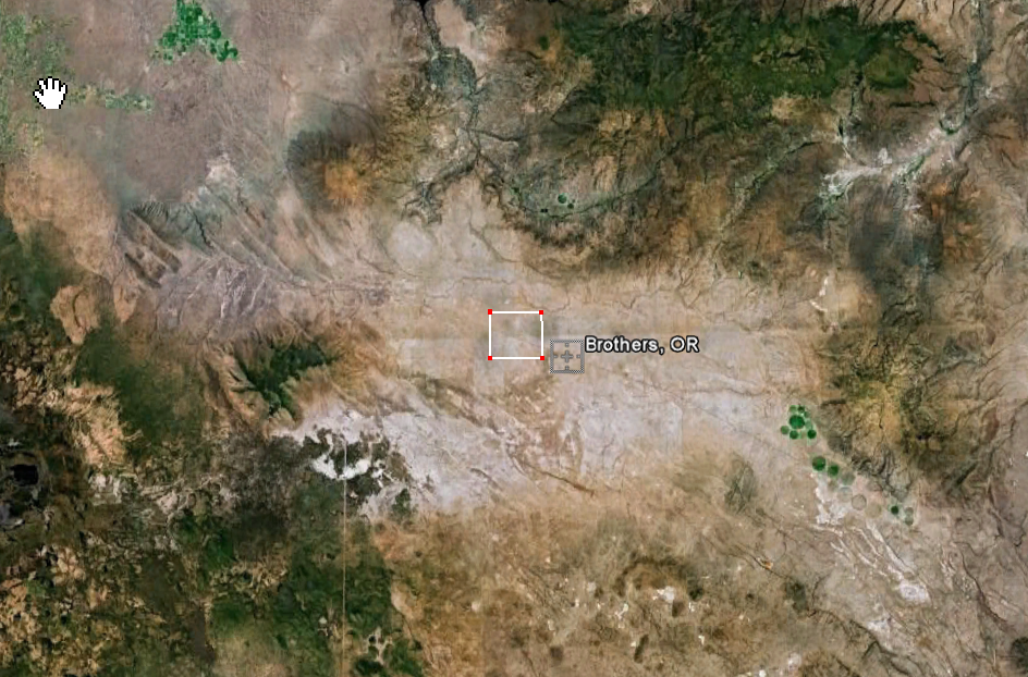
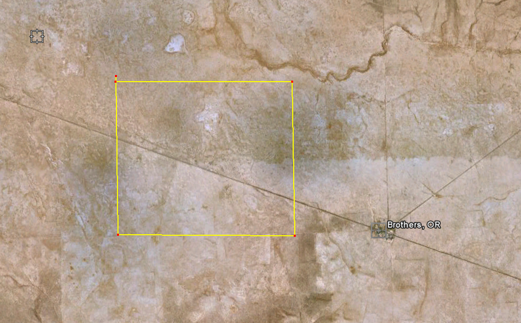
Now let imagine scaling this up by a factor of 10 to 640 MW to serve Eugene. What kind of footprint would that have in say a sunny location in Eastern Oregon?